You may not take time to look up when you enter a new room, but the ceilings of our buildings play an important role in how that space feels and operates. Lighting, color, material, and texture can make a space feel bright and airy, or warm and cozy.
In addition, required devices like light fixtures, smoke detectors, sprinkler heads, exit signs, ceiling fans, and HVAC diffusers control our comfort levels and make a space safe.
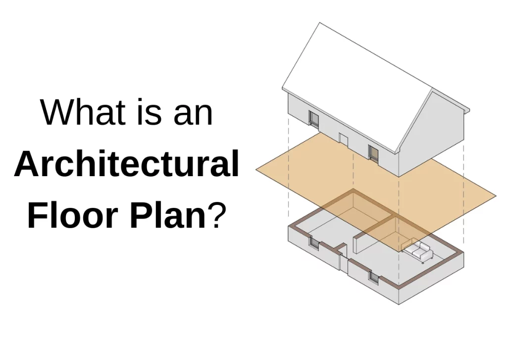
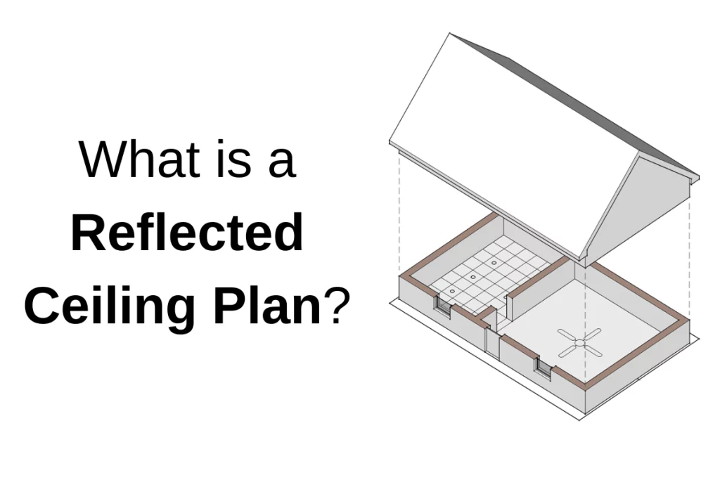
What is a reflected ceiling plan?
A reflected ceiling plan (referred to as an RCP for short) is an architectural drawing showing all the components listed above together. If you were to imagine the floor of a room as a mirror, what you would see in the mirror is what is drawn in the reflected ceiling plan. The “mirror” is typically imagined at a few feet above the floor plane so that elements like furniture and base cabinets are not included in the drawing. In some cases, however, furniture will be shown in gray or dashed because the lighting layout and furniture layout often influence one another. Their relationships are also helpful for the contractor to understand.
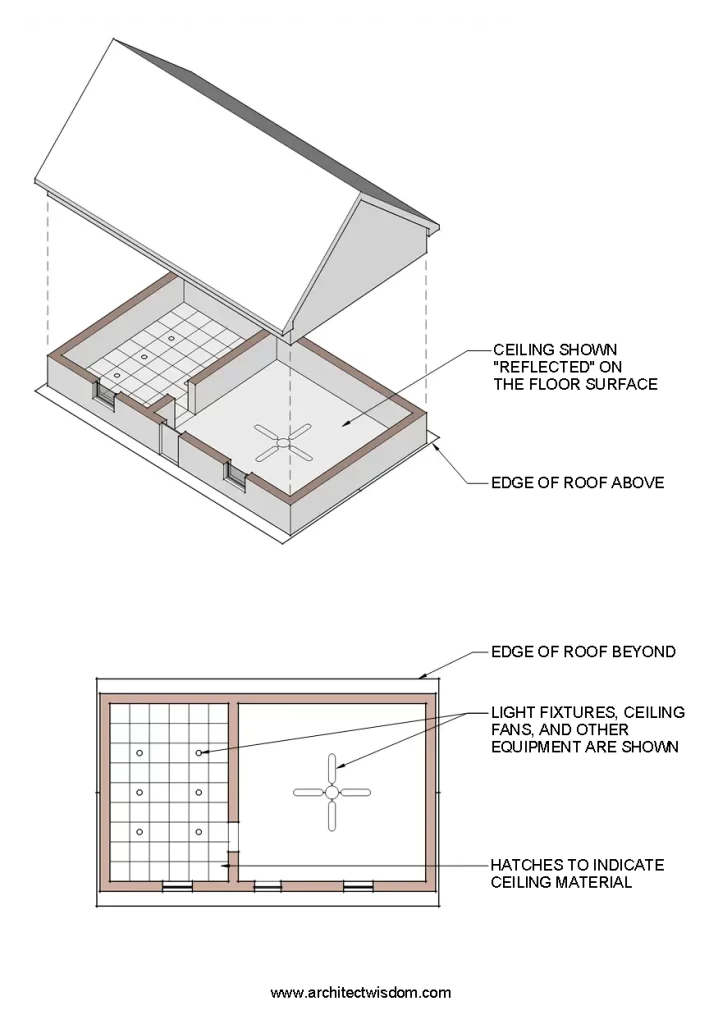
The reason why RCPs aren’t drawn looking up is that the plan would be flipped on paper. It’s less confusing to keep the building and spaces oriented the same on all the drawings.
Reflected ceiling plans should be drawn at the same scale as the floor plans to make cross-referencing them easy and to keep the drawings legible.
Reflected ceilings plans are often referred to as just ceilings plans for short, and the two terms are used interchangeably.

What does a reflected ceiling plan show?
RCPs are architectural drawings that often include elements from other trades to be located and coordinated by the architect. The most important items to include in a reflected ceiling plan are:
- The type and construction of ceiling assemblies
- The heights above the floor of ceilings and soffits
- The pattern and orientation of ceiling materials (like acoustic tile or wood paneling)
- Dimensions and alignments of elements and differing ceiling types
- The location of light fixtures, and other notable elements like projectors, speakers, exit signs, etc.
- A legend indicating what symbols and patterns mean
There are some elements that may or may not be shown on the RCPs. These items depend on the contractual relationship between the architect and the MEPFP engineers. It also depends the size and complexity of the building. Here are a few of those considerations:
- For houses and small commercial jobs, the type of light fixtures, switches, and other electrical equipment are shown in the RCPs and drawn by the architect or designer.
- For the majority of commercial jobs, architects choose the location of light fixtures and will dimension them on their drawings, but the type of light fixture, switches, occupant sensors, etc. are indicated on the electrical drawings.
- Similarly, HVAC equipment like diffusers, registers, and grilles are often located by the architect, but the specifics and size are determined by the mechanical engineer and indicated on the mechanical drawings. For exposed ceilings, coordination with ductwork, light fixtures, soffits, and devices becomes increasingly important, so showing everything “for reference” on the architectural drawings is helpful.
- There’s less flexibility with sprinkler heads and life safety items like exit signs and smoke detectors, but for important spaces, the designer will often have an opinion about alignments and locations, provided that all codes are met. Many of these items can be handled with typical notes or details. An example of this may be a note stating that “sprinkler heads to be located in the center of a ACT tile unless noted otherwise”.
- For exposed sprinkler lines, the architect may want the piping to lay out in a certain way. Since this may have price impacts (as with most exposed HVAC, electrical, or fire protection equipment), it’s better to include them on the construction drawings rather than work it out in shop drawings.
For some projects, the MEPFP designers are not under contract with the architect, or the scope may be design-build. In these cases, much of the coordination must be done with shop drawings and/or in the field.