Foundations create stability and a base for our buildings. They are the first portion of the building to be constructed, so getting it right is essential to the construction of the remainder of the building. The key to designing a stable building starts with the foundation plan.
What is a foundation?
A foundation consists of the elements of the building that is in contact with the earth. Foundations are structural and transfer gravity loads down to the ground. They also serve to resist lateral loads (wind and seismic) to keep the building standing and stable.
In areas where the ground freezes, the foundation extends down below the frost line to keep the lowest floor from damage from frost heaves.
What is a foundation plan?
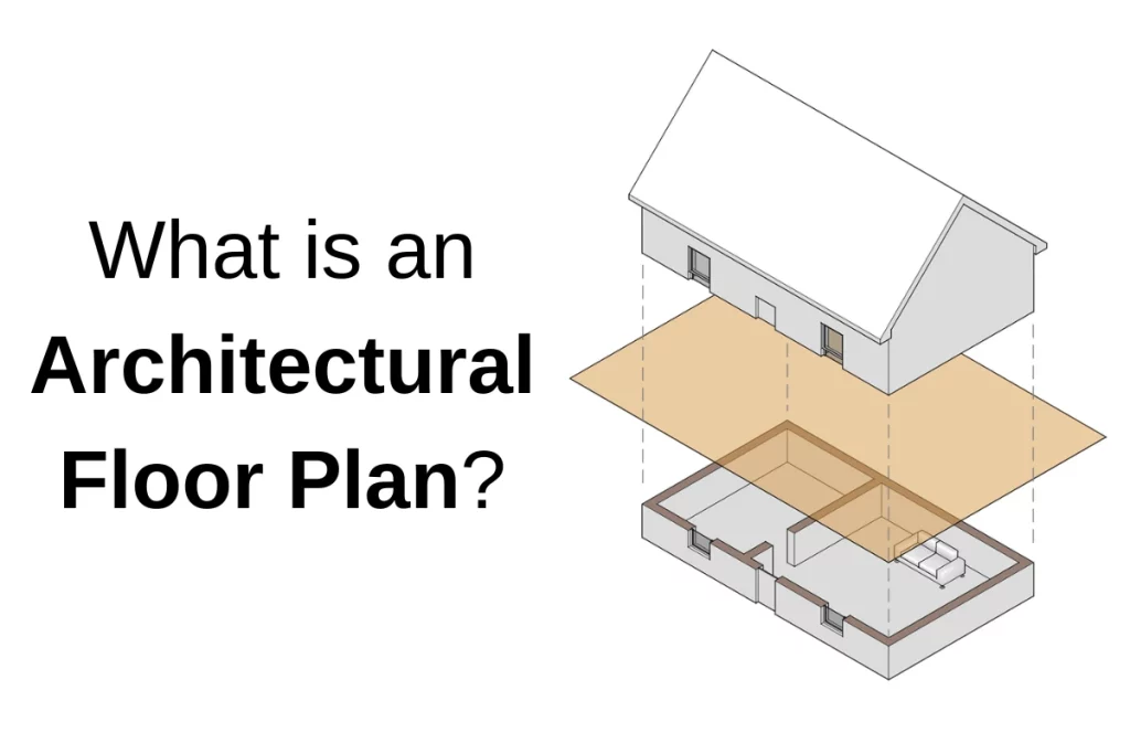
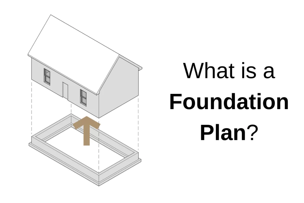
A foundation plan is precisely as it sounds – a drawing that illustrates the foundation of a building. Instead of using an imaginary cutting plane some distance from the floor level like in a floor plan, a foundation plan is drawn as if all of the construction built on the foundation is removed and the viewer is looking down on the foundation from above.
The foundation plan helps to isolate the concrete work (done by a concrete subcontractor) from the other work, like the carpentry and framing work.
Who designs a foundation plan?
Foundation drawings may be drawn by a structural engineer, an architect, or both.
Architectural foundation plans
Foundation drawings created by architects will indicate the dimensions and layouts of foundation walls. The architect sets the floor elevations and often dictates where brick shelves or stem walls are needed. A foundation plan can serve as a key for the foundation details to be called out. Features like doors, windows, louvers, or areaways are also called out on this drawing if their construction impacts the foundation.
The architect can use this drawing to coordinate under-slab utilities like sanitary lines, underground conduits, or SSDS systems with the foundation, footings, and other utilities. The plan can be shared with the other trades to help them coordinate their work and to overlay their drawings.
Foundation drawings drawn by structural engineers include all the information they are responsible for. The drawing may consist of the thickness of concrete foundation walls, rebar sizing and spacing, the thickness of slabs, rebar, footing sizes, grouting requirements of CMU, etc. These are the elements that have been designed based on the loads created by the building and the geotechnical conditions of the site.
The structural engineer and architect work together, going back and forth, to ensure that both of their requirements and needs are met.
Not all projects require the architect to create a foundation plan. Simple foundations that only require a few details to understand can be covered by the structural engineer and typical architectural details. In fact, the designer needs to ensure that they only include information within their scope of work as this could lead to discrepancies in the drawings, or worse, open the designer up to liability should something go wrong.
I’ve found in my experience that if I need to draw a foundation plan to solve design issues, coordinate trades, or communicate with the structural engineer, it will only help the contractor to understand as well. Some architects will decide that once the work is coordinated and the structural drawings are correctly drawn, there is no need for an architectural foundation plan.

What is typically included in a foundation plan?
Architectural foundation plans usually include the following:
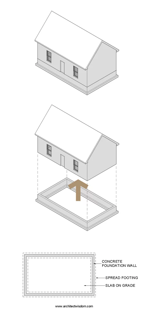
- Foundation walls
- Gridlines
- Footings for foundation walls (typically shown dashed)
- Columns or piers and their associated footings
- Any brick shelves and stem walls
- Openings for doors, windows, louvers, etc.
- Sleeves of significant size for utility connections or future work
- Dimensions
- Notes and keynotes relating to the architect’s scope of work
- Callouts indicating architectural details
Structural foundation drawings typically include:
- Everything architectural drawings show, with the exception of architectural notes or callouts
- Elevations indicating the top of wall, bottom of footing, etc.
- Footing and/or pier schedules
- Information regarding the slab construction
- Notes and keynotes relating to the structural engineer’s scope of work
- Callouts indicating structural details
It’s best practice not to duplicate information within the drawings. If the architect and structural engineer are both providing foundation drawings, they must discuss who is showing what information. From the contractor’s point of view, having all the information in one place is easiest. However, it’s the contractor’s responsibility to look at all the drawings for coordination purposes.
Basement Plan vs Foundation Plan
Basement plans and foundation plans may appear the same, but there are some important distinctions.
A basement plan is similar to a floor plan in that it’s created by using an imaginary horizontal plane to “slice” the building and remove everything above the slice. This view cuts through the foundation walls and looks downward. Since a basement is a habitable space, it must illustrate all of the information typically shown on any floor plan (room labels, finish floor elevations, door tags, etc.) For more information about floor plans, check out this article.
Foundation plans are a view looking down from above at the top of the foundation, omitting any construction that is built on top of it. It’s meant to illustrate the construction of the foundation that doesn’t include habitable space.