The architectural plans are the heart and soul of any drawing set. The initial concept of a building often begins as a plan sketch. Design ideas continue to be tested in plan until the scheme is ready to be brought to the next level. Floor plans are usually the first drawings hard-lined and serve as the base for all of the other trades to overlay their graphics.
What are architectural plans?
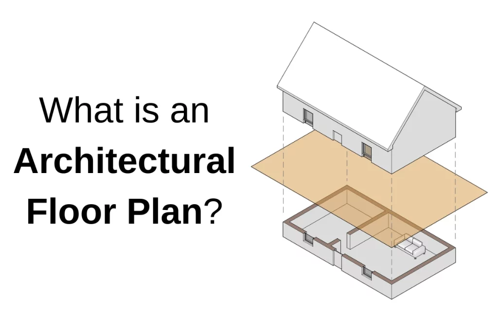
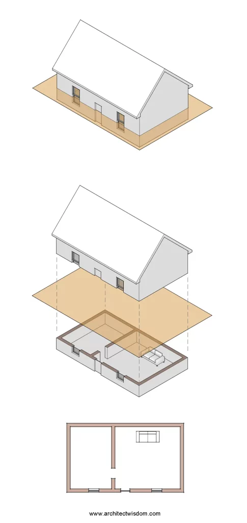
A floor plan is a 2D orthographic drawing that cuts a building parallel to the ground plane and looks towards the ground. The “cut” is usually made around 4 ft above the floor level so that doors and windows are cut through, and things like furniture and countertops are seen from above. Floor plans should be drawn to scale, usually 1/8″=1′-0″ for construction documents, but can vary based on the specific needs of a project.
“The plans” is a term often used when referring to the drawing set as a package. “The plans” include more than just floor plans; they include elevations, sections, details, notes, and tabular information. However, a plan drawing is as described above.
For buildings with multiple stories, plans will be made at every level so that each story has an associated floor plan.
Floor plans have many uses. Plans may be used to communicate to a client what the design or layout of the building is during the design phase. Floor plans can serve as the starting point for a builder or cost estimator to develop estimated project costs to prepare a budget. They can be used to obtain building permits or seek zoning or regulatory approval.
What do architectural plans show?
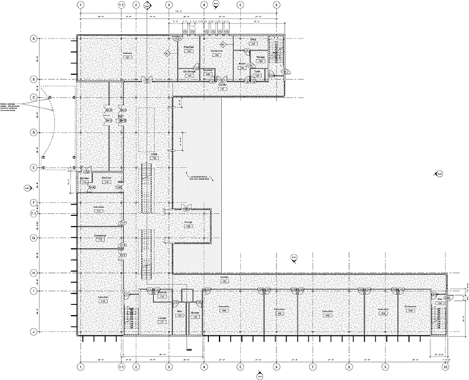
The floor plans can give the viewer an overall impression of the building. You can see where spaces are, how they relate to each other, where you enter and exit, and they serve as a key to find where other drawings are in the drawing set. The floor plans should contain the following:
- Dimensions including the overall building dimensions, locations of doors and windows, location of interior walls, etc.
- Structural grid lines
- Wall types. This communicates the construction of interior and exterior walls to the reader. It can be done graphically (with a hatch, for example) or with wall tags.
- Callouts. These indicate where interior and exterior elevations, building sections, wall sections, details, and enlarged plans can be found in the drawing set.
- The location of equipment. This could range from fire extinguishers to mechanical units.
- Text notes or keynotes explaining what items or assemblies are.
- Door tags. These connect each door to a schedule that provides all information for each door.
This isn’t a comprehensive list, but the basis for the beginning of a floor plan.
Types of floor plans
As projects get more complicated, there becomes a need to include more and more types of plans. This is because there’s only so much information that can be clearly illustrated on one drawing. Drafting any useful architectural drawing is a fine balance of clarity and efficiency; being sure to fill the page while also making the drawings legible.
Overall floor plans
These are plans that show the entire building in one drawing. For most houses or buildings a single overall floor plan can fit on a single sheet. In this case, the word “overall” is not needed.
Enlarged plans
Enlarged plans are required for portions of a building that need to be drawn at a larger scale. A larger scale allows the drawing to show greater detail and add more information that would not normally fit on the floor plan.
Areas like stairs, bathrooms, classrooms, or kitchens are commonly drawn as an enlarged plan because of the amount of information needed to explain the construction in that area.
Reflected ceiling plans
A reflected ceiling plan is a floor plan that describes the ceiling above it. Instead of looking up at the ceiling, the drawing “reflects” the ceiling onto the floor. These drawings are used to show ceiling construction types, indicate ceiling heights, show light fixture locations, soffits, diffusers, etc. You can learn more about RCPs here.
Site plan
Although a civil engineer typically picks up the site scope of work, it’s common for architects to include a site plan as well. Architectural site plans, most importantly, show which direction is north, connect the architectural finish floor elevation to the civil drawings finish floor elevation, locate the building relative to the property/setback lines, and give overall context to the building. They help to coordinate things like building entrances, loading docks, stoops or porches, flatwork, etc.
Some scope items like site stairs, site rails, and site lighting can create gray areas regarding responsibility. It’s essential for ownership of scope to be discussed and understood at the beginning of the project so that nothing is missed on the drawings. The path of egress ends at the public right of way, so an architect must ensure that the code is met up to that point.
You can learn more about site plans here.
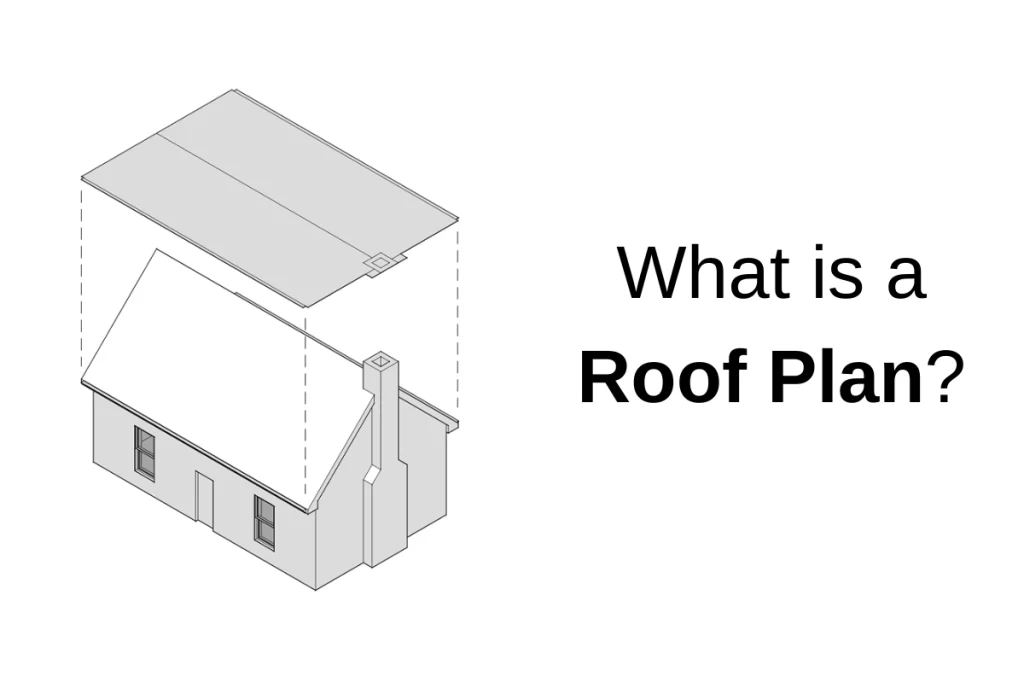
Roof plan
The roof plan’s primary goals are to describe the form of the roof and show how water is shed or removed from it. Things like roof slope, roof drains, scuppers, and roof materials are described on this drawing.
It also allows the architect to coordinate all of the trades that use the roof. Things like plumbing vents, mechanical equipment, ductwork, solar panels, and piping all need to be located.
We have more information about roof plans in this article.
Framing plan
Framing plans show the arrangement and type of structural members that support the roof or floor of a building. It also includes the required connections for those structural members. Framing plans are often drawn as a diagram (i.e., a dashed line may represent a beam rather than drawing the beam itself). Framing plans are usually drawn by a structural engineer but may be created by architects for smaller jobs and houses.
Foundation Plan
A foundation plan essentially removes all of the construction that is built on the foundation so that it can be viewed from above. More on foundation plans here.
Presentation plans
Presentation plans are created to convey certain ideas or information simply, usually to a specific viewer. Presentation plans may be rendered, use color, include diagrams, or use notes to communicate with the intended viewer while also omitting the technical information that’s not needed.
They are meant to allow people who may need help to read construction plans to understand the drawing and building more efficiently. They might be used to help viewers quickly comprehend the big picture, like in a zoning meeting, for example.
Plans that use color to illustrate room types or departments within a building can help the client or viewers to read the plans and see how spaces are located in relation to each other.
Furniture plans
Furniture is often laid out on the floor plans for planning purposes but usually included in the architect’s or contractor’s scope of work. Knowing where the couch and TV in a living are will dictate where outlets, data connections, light fixtures, and switches are located. Furniture can also help the viewer understand how big or small the space is.
For some projects, a plan dedicated to furniture is required, especially when choosing the furniture is part of the scope of work of the design team. Spaces like classrooms, libraries, and offices depend on furniture to function and for space definition. For these types of projects, a plan that identifies each piece of furniture is used. The furniture is tagged, and a schedule is produced to indicate the name, manufacturer, color, etc.
Finish plans
Finish plans are useful to indicate floor types, colors, and/or the patterns associated with that floor. Finish schedules or specifications will list the floor material, but having a visual representation can help a builder easily understand alignments, relationships, and where floor types blend into each other.
Other elements like threshold types between floor finishes or wall paint colors might also be indicated on a finish plan.
Code plans
Code plans are used primarily to communicate to two parties: the builder and the code official.
Code plans will illustrate to the viewer that the building meets the requirements of the applicable building codes. It is often paired with a table that lists the applicable codes and code requirements. For instance, the code plan might dimension the length of a dead-end corridor, indicate the occupant load of a single space, or illustrate the total path of egress travel.
These plans are also important as they are used to indicate any and all walls that are fire rated. This makes it clear to any reader where fire or smoke separations between spaces are made.
Notes are also often added to highlight unique or questionable situations. The note will indicate the applicable code sections and how that particular item meets that code.
Mechanical, electrical, plumbing and fire protection plans
With the exception of single-family houses and small commercial buildings, these plans are typically produced by a licensed engineer in the respective field. They use the architectural drawings as a base to overlay their information. Each trade can then indicate whatever information they need to for the contractor to understand, price, and build their scope of work.
Site plan, utility plan, grading plan, landscape plan, etc.
There are usually a series of plans showing all the site work to be done outsidethe building. These drawings may be done by an architect on a small project or home but are most often done by a licensed civil engineer and landscape architect.
These drawings can show town or city officials how a building will connect to the public utilities, will satisfy zoning requirements, show new curb cuts, landscape buffers, parking or how rainwater will be controlled on-site.
Site contractors can use this information to estimate the cut and fill requirements of the project, estimate trenching and utility work, see the landscaping requirements, and understand any sidewalks, patios or hardscape work to be done.
With our office expansion plans taking shape, my colleague is eager to hire an architectural planning service to transform our workspace into a functional and aesthetically pleasing environment. The excitement stems from envisioning a collaborative and innovative office layout that reflects our company’s values and fosters creativity among the team. Thanks for letting us know that floor plans serve a variety of purposes, and during the design stage, they may be used to explain to a client the layout or design of the structure.