The term “site” refers to the construction area on a parcel of property, or portion of a parcel of property, where construction and work occur. This work might be anything from paving and landscaping to the construction of a skyscraper.
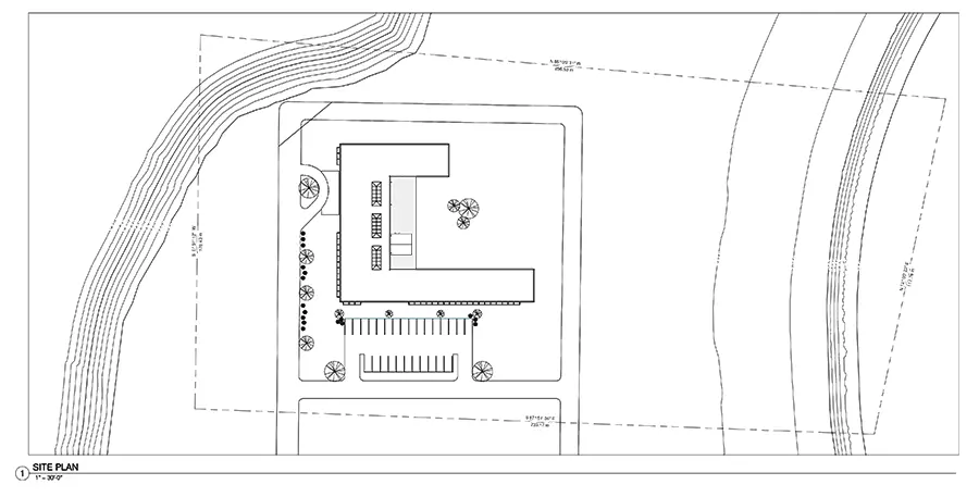
Therefore, a site plan is a 2D orthographic drawing that represents the construction site from above and illustrates existing and/or proposed site conditions.
- Types of Site Plans
- What should a site plan generally include?
- General information
- The Building(s)
- Finish Floor Elevations
- Property Lines
- Setbacks, Easements, Rights of way
- Natural Features: Plantings, Bodies of water, Wetlands, and Landscape Elements
- Man Made Features: Roads, Parking, Sidewalks, and Access Points
- Context
- Existing Utilities and Proposed Tie-ins
- North Arrow and Scale
- Civil Site Plan vs Architectural Site Plan
Types of Site Plans
There are various types of site drawings that each focus on a specific set of information. How many drawings are needed for a project is dictated by the scope of the work to be done and how complicated that scope is. Homes and simple buildings or renovations may only need a survey and a single site plan. More advanced construction projects may require most or all of the drawings listed below.
Here are many of types of site plans common in construction:
- Site survey – Drawn by a surveyor to document site boundaries and current site conditions. The starting place for any site drawing.
- Architectural site plan – These are typically included with the architect’s drawings and show the location and orientation of a building(s)
- Existing / Demo plan – This drawing shows the existing conditions of the site and how those conditions will be altered or removed
- Proposed Site Plan – Shows all of the new sitework to take place
- Grading Plan – This drawing shows the existing and proposed topography and spot elevations
- Utility Plan – Shows existing and proposed utilities and how they will tie together
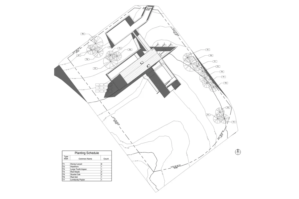
- Landscape plan – Shows the types of plants and ground cover to be installed as well as more detailed paving patterns or site elements (like trellises, bike racks, fences, etc.)
- Layout and materials plan – This drawing shows the specifics of parking layouts, curbs, paving, etc.
- Soil, erosion and sediment control plan – this drawing is often required by the city or town to show how the construction will mitigate any impacts on the construction site’s surroundings
- Drainage plan – shows how water flows, is absorbed, or discharges from a site. Often this information is combined with another drawing, typically with the utilities or the grading plans.
What should a site plan generally include?
The site plans listed above (with a few exceptions) should contain all the following information. As I stated before, most of the site work can be communicated on a single drawing for single-family houses, but this depends on the jurisdiction in which you’re building and the scope of work to be done.
General information
Most of the basic information will be part of the title block, but all drawings should include:
- Name and contact information of the owner
- Address of project
- Name and contact information of the engineer/designer
- The source and date of the site survey
- An indication of the extent of the area of work
The Building(s)
There are plenty of construction jobs that don’t include a building, but on the jobs that do, the building or addition is often the focal point. Showing its footprint and dimensioning its location from the property line is the starting point for any proposed site plan.
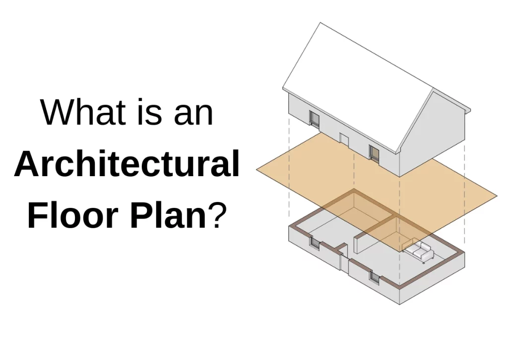
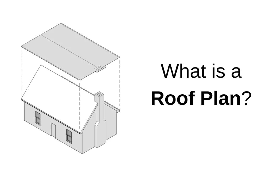
There are a few ways to represent the building on a site plan. Most often, the building is just represented as a footprint or outline. It’s also common to show the roof of the building as if you’re looking down on the site from the sky.
Sometimes, an architect will prefer to show the first floor plan so that the relationship between exterior and interior spaces can be seen.
Finish Floor Elevations
A site plan must include the finish floor elevation of any new buildings on the site. This is important because architectural drawings usually show elevations relative to the first floor level, which is often set at 0′-0″. However, the contractor needs to know what that first floor level is relative to the surrounding topography.
Property Lines
Property lines define the legal boundary of a piece of land. Obtaining a professional survey is the starting point of any building project. Surveyors visit the site and will accurately draw the property lines based on a field survey. To find the corners of the site, there are often granite place markers, rebar driven into the ground, wood stakes, or nails driven into the sidewalk or a tree. Surveyors will also review legal documents that may describe the site’s boundaries to make their drawings.
Setbacks, Easements, Rights of way
Most, if not all, municipalities have zoning ordinances that will require certain setbacks from the property line for site work. This provides “buffers” from buildings to neighbors and the street. The ordinance can usually be found on your city’s website, or you can contact the town planning department.
In addition, easements or rights of way may limit where construction can be done. These are legal agreements that allow other entities to utilize the land. The most common easements are for utility companies whose infrastructure runs through a property. Another common easement is an access easement that connects a parcel of land to a public right of way.
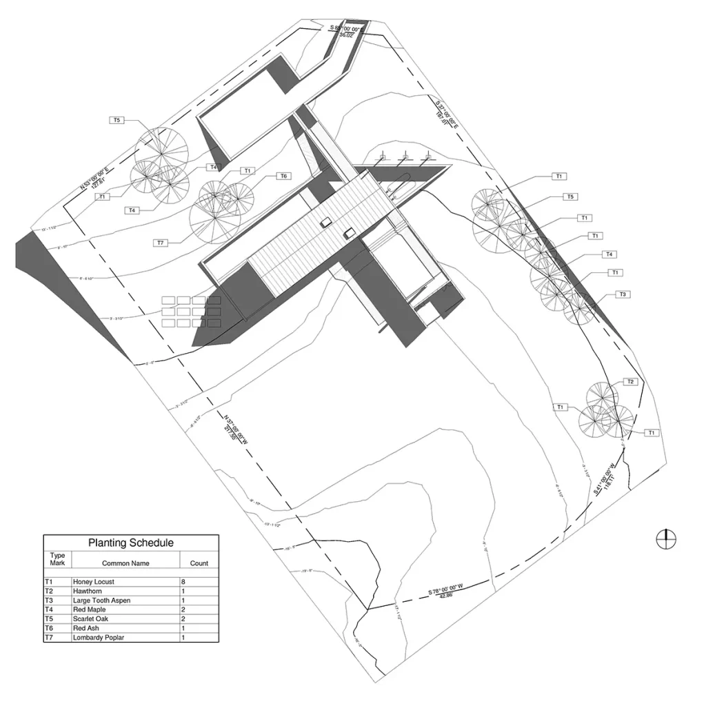
Natural Features: Plantings, Bodies of water, Wetlands, and Landscape Elements
It’s important first to document and draw all of the existing features of a site. These will often inform where buildings, paving, and new plantings are located. Elements like wetlands and ledge will be impossible or problematic to build on, while existing trees are easier to remove if needed. Once the existing features are understood, the designer can demolition and add new features on the drawings as they see fit.
Man Made Features: Roads, Parking, Sidewalks, and Access Points
All of the existing conditions need first to be documented. Then a proposed design can be laid over that information. The proposed design needs to show curb cuts, driveways, access to the site, parking, sidewalks, flat work, and other paving work. It must differentiate between existing, demo, and new work to be completed.
Context
The context is all of the surrounding elements that may or may not influence the design of the building. This may be limited for rural sites, but is most important for urban sites. The location of neighboring buildings and roads can play a significant part in the design of the new work.
Existing Utilities and Proposed Tie-ins
The design team will need to know where there are public utilities available (water, sewer, gas, and electricity). This is usually documented on the survey. Once they locate what’s existing, the design team can determine how the new work can tie into it. This will include coordination with, and approval from, the utility company.
North Arrow and Scale
A north arrow should always be included as a way to orient the site and building to the rest of its surroundings. A scale should always be included so that sizes and distances can be measured and understood.
Civil Site Plan vs Architectural Site Plan
The site work (and site plan) is typically designed and over seen by a civil engineer or landscape architect. They will develop a series of drawings and specifications that identify the work and ensure that it meets zoning requirements and code.
This work is typically coordinated with the architect. Oftentimes the architect will have thoughts or insights on the design of the landscape. They will want to work with the civil engineer to ensure that access to the building is appropriate, accessible routes are created, and exterior spaces are provided per the clients wishes and the requirements of building codes.
Because of this, architects will usually create an architectural site plan that they can use to coordinate with the civil engineer or landscape architect. There are some items that do fall within the architect’s scope of work. For example, egress continues until the occupants get to the public right of way, so ensuring that things like handrails and slopes meet the code is part of their scope of work.
All three entities (civil, architectural, landscape) will likely show the work designed by the others for reference. A cohesive and coordinated set of drawings will make understanding the work to be done easier for the client and the contractor. However, the notes, dimensions, and details should only be included on the appropriate designer’s drawing set. For example, the drawings will all show parking lot striping, but the civil engineer is the one to indicate the size and spacing of parking spots.