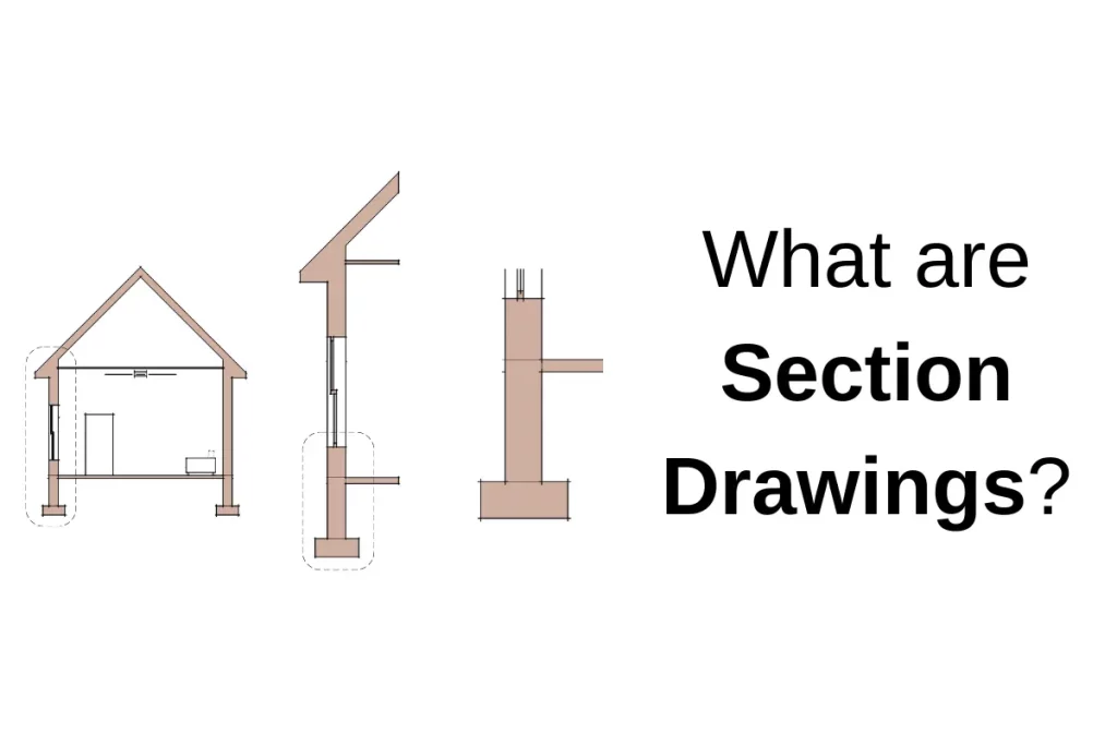
Section drawings are a critical part of any construction drawing set. They slice the building up at several scales to show the materials and assemblies being used, spatial relationships, and information that can’t be clearly indicated on the plans or elevations. I’ll break down the several types of section drawings below.
What is a section drawing?
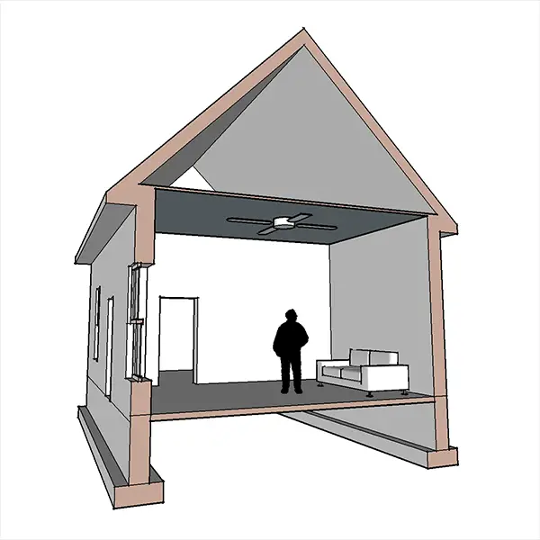
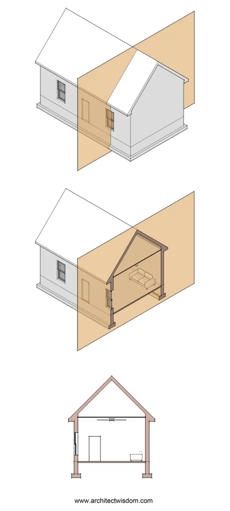
A section is an orthographic 2D drawing that uses an imaginary vertical plane to “cut” the building. On one side of the plane, the building is removed so that the construction of whatever is sliced can be seen. The slice is typically made perpendicular to the wall it is cutting through. It may or may not show the building elements in elevation beyond.
Architects use sections of different scales to explore how all the components fit together, but usually consist of three: building sections, wall sections, and section details (more on each below). They could be used to illustrate a large volume within the building or describe how a rafter meets the top plate of a wall. Once these conditions are figured out, the final drawings communicate these conditions to the contractor.
The sections are generally cut through the entire building, through typical conditions (explained here), unique spaces, complex volumes, and a-typical conditions that need more explanation. The drafter will need to draw as many sections as required to explain the construction of the building, but no more. Slight variations can often be inferred from the typical details or other drawings.
Sections are essential because when a building is only viewed in elevation, many of the elements seen cannot be fully understood. Elements like the profiles of cornices and moldings, the depth of an overhang, or the construction that holds the façade in place can’t be seen in elevation.
Likewise, for interior spaces, the arrangement of acoustic panels in an auditorium or the construction of open stairs in a lobby can’t be easily communicated only in the plans and RCPs.
How to read a section drawing?
You can read a section drawing once you understand that any element that has been cut through is represented with a heavier line weight which helps to make that portion of the drawing “pop.” The elements that are cut are then hatched, either generally showing that it’s a solid element or with a specific hatch to indicate the type of material. The voids will show everything beyond with a lighter line weight.
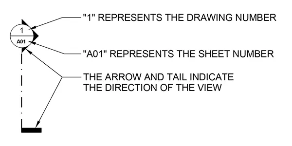
Section cuts are indicated on the plans and elevations with the following symbols below. In some cases, building sections may jog so that one drawing can slice through several important spaces that a single plane would not have cut through.
Types of architectural section drawings
There are a few different types of section drawings that are used in a construction drawing set. Each serves a specific role and is meant to indicate specific information.
There is a sort of hierarchy to section drawings – each section serves as a key for the section with the next level of detail. Below, the types of sections are described from the smallest scale (showing the largest portion of a building) to the largest scale (showing the most detail).
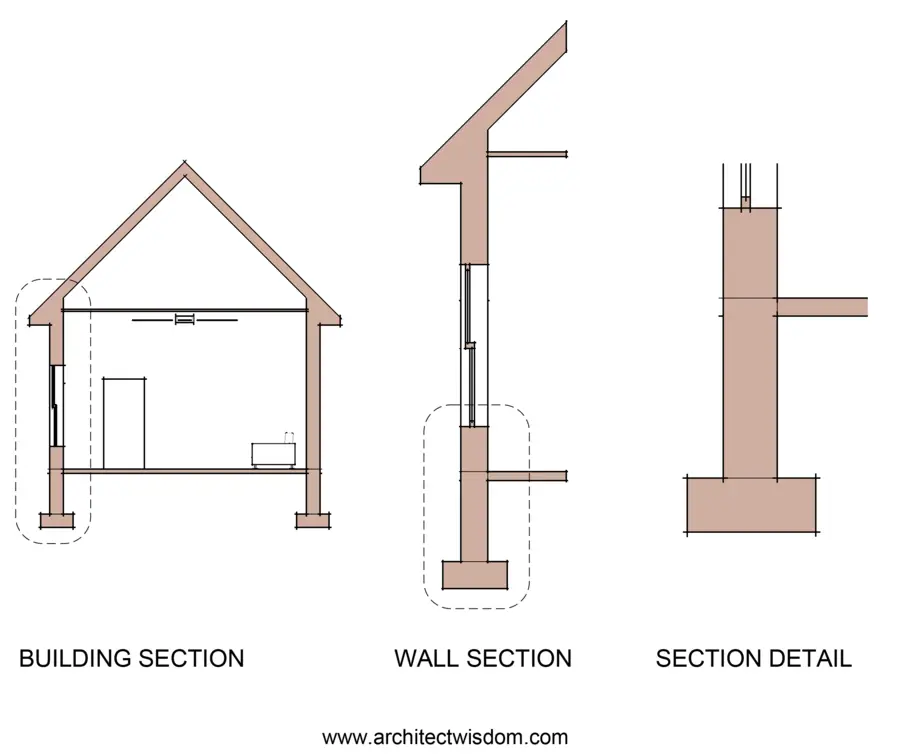
Building Sections
Building sections are created by slicing through the entire building from exterior wall to exterior wall. They are generally the scale of the exterior elevations (but sometimes smaller) and aren’t meant to have a lot of specific information or notes. In some cases, the walls, floors, roof, and other elements that have been cut through will be hatched as one pattern to simplify the drawing.
Building sections may call out general assemblies of the building (“typical exterior masonry wall construction,” for example). More importantly, they are meant to give an overall sense of spaces, the relationship between floor levels, the roof, atriums, and multiple-height spaces.
Building sections also serve as a key to show where wall sections have been cut through the building.
There are two general types of building sections that are described below.
Cross Section (AKA transverse section)
Cross-sections are building sections that slice a building in a shorter direction.
Longitudinal Section
Longitudinal sections are building sections that slice a building in the longest direction.
Wall Sections
Wall sections are vertical slices that focus on the construction of a specific wall, typically at the exterior. These are larger in scale than building sections, so more detail can be seen (typically 3/4″=1′-0″).
These drawings show how the roof meets the wall, the construction of the wall from roof to grade, and the subgrade foundation wall construction. It can also show any vertical changes in wall types, offsets in the wall, canopies, awnings, and overhangs. They use elevation datum to indicate key heights of building elements. For example, the top plate of a wood framed wall or the sill height of a window. They contain vertical dimensions and, in some cases, the number of courses in masonry construction.
Wall sections are useful to the designer to ensure that there is continuity from roof to wall to below grade in terms of weather barriers, vapor barriers, and thermal barriers (insulation).
Like the building sections are a key to wall sections, wall sections are the key to the details (described below).
Interior Wall Sections
In some cases, interior wall sections may need to be drawn. If there is important information that can’t thoroughly be described in the details, interior wall sections can fill the gap. They also allow the builder to see how an interior wall may be continuous (or not) from foundation to roof, like in the case of a shaft wall.
Another example could be a party or demising wall. These are critical elements to separate tenants or dwelling units from one another. Their construction is often fire rated, and the isolation of sound between those spaces needs to be maintained. A wall section can help the contractor see how the wall lands on a footing and continues to the underside or above the roof deck. In addition, callouts can be made if additional details are needed.
Stair and Elevator Sections
Stair and elevator sections are similar to interior wall sections but tend to show more context. An elevator section typically slices through the entire elevator shaft and perhaps part of the elevator lobby. This will allow the drafter to call out the necessary details to construct the shaft, show the elevator pit, the overrun, the hoist beam, etc.
Similarly, stair sections will show the entire stair from the lowest floor to the highest. They indicate the height from floor to floor, the number and size of risers in the stair, illustrate the guardrail and balusters, and show callouts indicating how the stair is constructed.
Detail Sections
Detail sections (typically referred to as just “details”) are an even larger scale drawing that hones in on one specific condition. They are typically drawn at scales between 1″=1′-0″ to 3″-1′-0″.
Details are the drawings that get to the nuts and bolts of how a certain condition is built. Specific materials, products, and sizes are indicated in the details, as well as dimensions, keynotes, elevation datums, roof slopes, or anything else to help communicate the construction intent.
It’s important that these drawings are drafted based on the actual sizes and shapes of the products shown. A building section might only show a window as two rectangles for the frame and a single line indicating the plane of glass. Here, the details created by the window manufacturer should be integrated and coordinated with the building’s details. This is a critical role of an architect: weaving all of the products and assemblies together.
Details are called out on the wall sections but can be called out anywhere else if that condition is not cut through in a wall section.
Plan details
Plan details are similar to section details but drawn in plan, meaning the section cut is taken horizontally instead of vertically. More on plans here.
Section Perspective
Section perspectives are not commonly used in construction documents. However, they are great presentation drawings that not only show the building in section but also the character of the interior and exterior spaces in 3D.