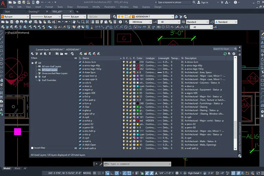
Drawing layers are the primary way CAD software organizes graphic information and controls that information’s visibility. With layers, drafting is easier because different layers can be identified with different colors. Line weights can be associated with layers in order to help printed drawings to read better. Layers can be turned off or on to overlay information or produce additional drawings.
Why follow national standards?
Although there is some initial time investment in learning the standards, it’s very likely that some form of it will be used in your office. Developing company standards for anything has its benefits, but here are some specific advantages to creating CAD standards.
- Saves time by eliminating the guesswork on how to organize a drawing
- Create a template with drawing standards in place can allow you to get started quickly
- Establishes a graphic quality so drawings can look consistent
- Team members (inside and outside of the office) are familiar with the drawing structure and can access information more efficiently
- Easier for consultants and users outside of your organization to use your CAD files
Does the AIA establish CAD standards?
Not exactly. The American Institute of Architects established “CAD Layer Guidelines” for the first time in 1990. In 1997, the AIA decided to collaborate with the National Institute of Building Sciences to combine the “CAD Layer Guidelines” and NIBS’s “National CAD Standard”. These two organizations continued to work with other groups, like the Construction Specifications Institute (CSI), to further develop the U.S. National CAD Standards for Architecture, Engineering, & Construction into what it is today.
Version 6 is the current iteration of the National CAD Standards. More information can be found here.
Layer format
When naming layers, the following format is used:
Discipline Designator – Major Group – Minor Group – Minor Group – Status

Discipline Designator: Indicates discipline (civil, fire protection, plumbing, survey, etc.)
Major Group: Indicates major building system (door, glazing, furniture, roof, etc.)
Minor Group: Further defines the building system
Status: Indicates the phasing (existing, demo, new, temporary, etc.)
The first two parts (discipline designator and major group) are required. The following three can be used to better describe the layer and are optional.
Note: “X” in the tables below is a placeholder for any letter.
| Architectural Discipline Designators | |||
|---|---|---|---|
| Designator | Description | ||
| A | Architectural | ||
| AS | Architectural Site | ||
| AD | Architectural Demolition | ||
| AE | Architectural Elements | ||
| AI | Architectural Interiors | ||
| AF | Architectural Finishes | ||
| AG | Architectural Graphics | ||
| AJ | User-Defined | ||
| AK | User-Defined | ||
| Architectural Layer List | |||
|---|---|---|---|
| Layer Name | Description | ||
| AX-XXXX-FNSH | Any major group: finishes | ||
| AX-XXXX-CASE | Any major group: casework | ||
| AX-XXXX-FIXT | Any major group: plumbing fixtures | ||
| AX-XXXX-GRID | Any major group: grid | ||
| AX-XXXX-SIGN | Any major group: signs | ||
| AX-AREA | Area | ||
| AX-AREA-OCCP | Area: occupant or employee names | ||
| AX-CLNG | Ceiling | ||
| AX-CLNG-ACCS | Ceiling: access | ||
| AX-CLNG-OPEN | Ceiling: openings | ||
| AX-CLNG-TEES | Ceiling: main tees | ||
| AX-CLNG-SUSP | Ceiling: suspended elements | ||
| AX-COLS | Columns | ||
| AX-CONV | Conveying systems | ||
| AX-DOOR | Doors | ||
| AX-DOOR-FULL | Doors: full-height (swing and leaf) | ||
| AX-DOOR-PRHT | Doors: partial height (swing and leaf) | ||
| AX-EQPM | Equipment | ||
| AX-EQPM-ACCS | Equipment: access | ||
| AX-EQPM-FIXD | Equipment: fixed equipment | ||
| AX-EQPM-MOVE | Equipment: moveable equipment | ||
| AX-EQPM-NICN | Equipment: not in contract | ||
| AX-EQPM-OVHD | Equipment: overhead | ||
| AX-FLOR | Floor | ||
| AX-FLOR-CASE | Floor: casework | ||
| AX-FLOR-EVTR | Floor: elevator cars and equipment | ||
| AX-FLOR-HRAL | Floor: handrails, guard rails | ||
| AX-FLOR-LEVL | Floor: level changes, ramps, pits,depressions | ||
| AX-FLOR-OTLN | Floor: outline | ||
| AX-FLOR-OVHD | Floor: overhead (objects above) | ||
| AX-FLOR-RAIS | Floor: raised | ||
| AX-FLOR-RISR | Floor: stair risers | ||
| AX-FLOR-WDWK | Floor: architectural woodwork | ||
| AX-FURN | Furnishings | ||
| AX-FURN-FILE | Furnishings: file cabinets | ||
| AX-FURN-FIXD | Furnishings: fixed in place | ||
| AX-FURN-FREE | Furnishings: freestanding | ||
| AX-FURN-PLNT | Furnishings: plants | ||
| AX-FURN-PNLS | Furnishings: system panels | ||
| AX-FURN-SEAT | Furnishings: seating | ||
| AX-FURN-STOR | Furnishings: system storage components | ||
| AX-FURN-WKSF | Furnishings: system work surface components | ||
| AX-GLAZ | Glazing | ||
| AX-GLAZ-FULL | Glazing: full-height | ||
| AX-GLAZ-PRHT | Glazing: partial-height | ||
| AX-GLAZ-SILL | Glazing: window sills | ||
| AX-HVAC | HVAC | ||
| AX-HVAC-SDFF | HVAC: supply diffusers | ||
| AX-HVAC-RDFF | HVAC: return air diffusers | ||
| AX-LITE | Lighting fixtures | ||
| AX-ROOF | Roof | ||
| AX-ROOF-HRAL | Roof: handrails | ||
| AX-ROOF-LEVL | Roof: level changes | ||
| AX-ROOF-OTLN | Roof: outline | ||
| AX-ROOF-RISR | Roof: stair risers | ||
| AX-ROOF-STRS | Roof: stair treads, ladders | ||
| AX-WALL | Walls | ||
| AX-WALL-CAVI | Walls: cavity | ||
| AX-WALL-CNTR | Walls: centerline | ||
| AX-WALL-FIRE | Walls: fire wall | ||
| AX-WALL-FULL | Walls: full-height | ||
| AX-WALL-HEAD | Walls: door and window headers | ||
| AX-WALL-JAMB | Walls: door and window jambs | ||
| AX-WALL-MOVE | Walls: moveable partitions | ||
| AX-WALL-PRHT | Walls: partial-height | ||
| AX-WALL-PATT | Walls: texture or hatch patterns | ||
There are a few other layers used to organize the drawings that can help indicate the type of drawing or annotations used throughout the drawing.
| View & Annotation Layer List | |||
|---|---|---|---|
| Layer Name | Description | ||
| XX-XXXX-DETL | Detail | ||
| XX-XXXX-ELEV | Elevation | ||
| XX-XXXX-SECT | Section | ||
| XX-XXXX-ANNO | Annotation | ||
| XX-XXXX-DIMS | Dimensions | ||
| XX-XXXX-IDEN | Identification tags | ||
| XX-XXXX-KEYN | Keynotes | ||
| XX-XXXX-LABL | Labels | ||
| XX-XXXX-LEGN | Legends, symbold keys | ||
| XX-XXXX-MARK | Markers, break marks, leaders | ||
| XX-XXXX-MATC | Match Lines | ||
| XX-XXXX-NOTE | Notes | ||
| XX-XXXX-NPLT | Non-plotting graphic information | ||
| XX-XXXX-RDME | Read-me layer (non-plot) | ||
| XX-XXXX-REDL | Redlines | ||
| XX-XXXX-REFR | Reference, external files | ||
| XX-XXXX-REVC | Revision clouds | ||
| XX-XXXX-REVS | Revisions | ||
| XX-XXXX-SCHD | Schedules | ||
| XX-XXXX-SYMB | Reference Symbols | ||
| XX-XXXX-TEXT | Text | ||
| XX-XXXX-TABL | Data Tables | ||
| XX-XXXX-TITL | Drawing or detail titles | ||
| XX-XXXX-TTLB | Border and title block | ||
How to use CAD standards in your practice
Whether you work alone or in an office, there are a few steps you should consider taking if you haven’t already. You should definitely start by setting up a template. Create a CAD file with all of the layers, colors, and line types set up. Create a plot style to go with it. This way, you can open it at the beginning of any project and be ready to go. Investing some time up front can pay dividends in the long run.
As you work on more projects, you’ll know what works well, what blocks you use, etc. and can build up a library. The more tools you have at your fingertips, the quicker you can put a set of drawings together.
Don’t have the time to put something together? Not sure where to start? There are a number of options out there to buy pre-assembled drawing templates that often have title blocks, CAD blocks, dimension styles, etc. ready to go.